All RO membrane elements are subject to scaling and fouling and the vast majority are subjected to
some attempt at cleaning. Formation of a fouling layer during continuous filtration can result in the
formation of both reversible and irreversible foulant layers. The irreversible fouling is normally caused
by strong attachment of particles, which is impossible to be removed by physical cleaning method [1].
The success of cleaning is very variable and is dictated by the type of foulant, chemistry used to remove
the foulant and the method used. Any improvement to the cleaning process will increase the operating
efficiency of the plant and decrease the frequency between cleans thus prolonging membrane life. The
authors have been investigating the effect that generated bubbles and microbubbles have on cleaning
reverse osmosis membranes. Compressed, injected air [2], [3], is used in cleaning and backwashing
membrane bioreactors, microfiltration and ultrafiltration membranes but has not been applied to reverse
osmosis (RO) membrane elements.
A direct result of the separation of water and particulate material by use of membranes is the
accumulation and deposition of material on the membrane surface. These processes are known as
fouling. Fouling is the result of concentration polarization of particulate material and dissolved solutes.
Fouling is a complex process and occurs mostly due to colloidal and scale precipitation as well as
microbial growth. Permeation through the membrane is achieved by pressure driven convective flow,
thus any fouling of the membrane surface will compact with time and lead to membrane flux decline. In
order to recover these flux losses, the foulant layer needs to be effectively removed by chemical
cleaning.
Bubbles and microbubbles can be generated by effervescing reagents producing gasses and by physical
introduction of a liquid air mix. The effectiveness of effervescent in cleaning reagents is well
documented and used extensively in the food and beverage industry and dental hygiene. Similarly the
use of bubbles and microbubbles is also well documented for cleaning in a variety of industries and for
different foulants. The cleaning effect occurs “when bubbles expand and collapse close to boundaries, a
shear flow is generated which is able to remove particles from the surface, thus locally cleaning it.” [4]
This phenomenon has been tested by numerous researchers notably Agarwal etal. “investigated the
potential of air micro bubbles for biofilm detachment from a nylon membrane surface in comparison to
chemical cleaning by sodium hypochlorite (NaOCl). About 88% of fixed biomass detachment was
observed after 1 h air microbubbling, while only 10% of biofilm detachment was achieved in the control
experiment without microbubbles.”[5] This effectiveness at removing biofilm is of particular relevance
for enhanced cleaning of RO membranes.
A series of experiments were initially ran on a membrane flat sheet test rig which demonstrated greatly
enhanced cleaning when using effervescent chemicals and a microbubble generator device as compared
with conventional cleaners. These results are presented in a separate paper. In order for this new
cleaning method to be adopted the authors thought it was necessary to investigate the potential for
membrane damage due to the use of bubbles in conjunction with cleaning reagents. This paper describes
the equipment used and experimental methodology to test different manufacturer’s membranes with the
new cleaning method. The membrane elements were then autopsied to look for any damage. The
autopsy results are presented here and show that none of the manufacturer’s membranes showed any
signs of physical damage or wear.
II. METHODOLOGY
In order to prove the concept and then simulate real life conditions two pieces of equipment were
designed, and built to run a series of experiments.
2.1 Flat sheet test rig
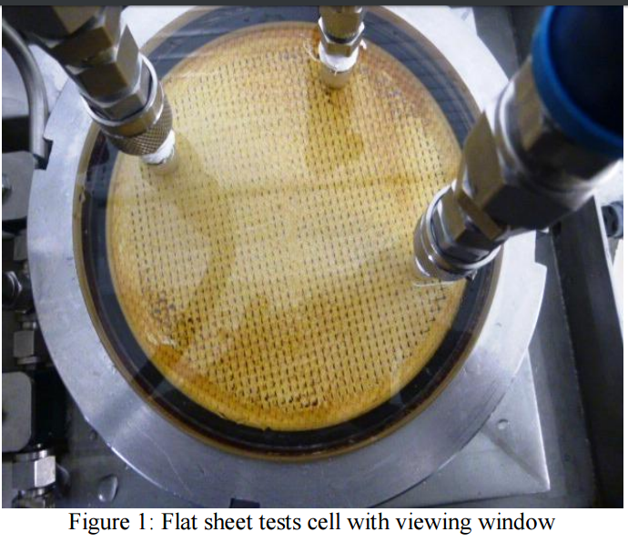
The flat sheet membrane test rig was used to characterize and evaluate the performance of fouled and
clean membrane samples. It consists of two stainless steel plates which accommodate fouled or clean
membrane samples, plastic spacer material and the permeate carrier. There is also a viewing window on
the feed/concentrate side that enables one to see the fouled membrane sample and cleaning progress.
The feed water is circulated around the system through the test cell at a known flow rate and
transmembrane pressure. The concentrate was returned to the feed tank with the permeate stream to
maintain a constant feed water concentration. Permeate samples are taken to measure the flux rate and
conductivity for salt rejection determinations.
The size of the membrane pieces used for testing on the flat sheet rig was ~0.023 m2
.
Each membrane sample was characterized according to the specific membrane manufacturers’
conditions for that membrane.
2.2 Pilot Plant
The 8″ Membrane Test Rig was used for characterization and cleaning of fouled membranes. It can also
be used to evaluate the performance of a fouled membrane before an autopsy was carried out. This can
give additional information such as differential pressure, salt rejection and the flux rate which can be
compared with design values. The rig comprises of carbon pre-filters, feed/CIP cleaning tanks, cartridge
filters, low pressure pump for cleaning, high pressure pump for membrane characterization, 1 and 3
element pressure vessels and pressure and flow transmitters.
2.3 Microbubble generator
The use of air together with cleaning chemicals for the cleaning of fouled spiral wound RO/NF
membranes was tested and evaluated.
The air bubbles were generated by two methods:
1) By use of a specially designed microbubble generator in the CIP line.
2) By use of proprietary powder cleaners. This was generated in situ by dissolution of the cleaning
products causing some effervescence.
The use of air-liquid to introduce small microbubbles using a specially designed generator was initially
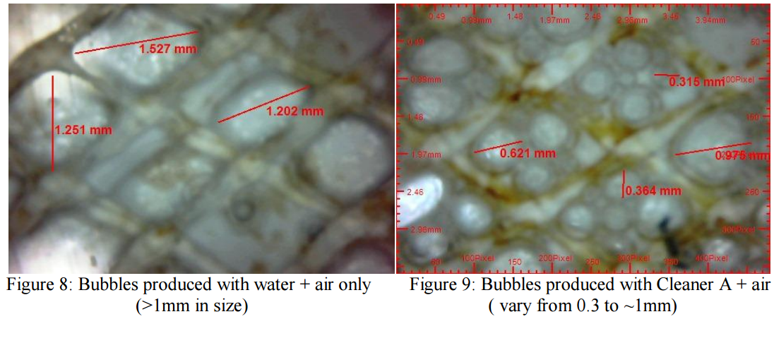
investigated in the laboratory using the Flat Sheet Rig. It was noticed that using only water and air
created large bubbles that quickly coalesced and had minimum impact on the membrane surface. A
dramatic change in the number and size of the bubbles was seen when using specially formulated
cleaning chemicals compared to commodity cleaners or water and air only (see Figures 8 and 9). In
order to optimize cleaning the bubble size is very important [6]. The proprietary cleaners produced a
large number of smaller bubbles. The formation of small bubbles increased the turbulence of the
cleaning solution mixture leading to an improved cleaning effect.
The air generator at atmospheric pressure was opened to allow sufficient air to enter and mix with the
cleaning solution creating small air bubbles that can be seen upon the return of the cleaning solution to
the CIP tank.
In order to investigate the effects of this concept on membrane performance, extensive tests were
performed using a variety of venturi-type devices along with a flat sheet test rig with a viewing window
to observe the mechanism of air bubbles during cleaning action. To achieve optimal cleaning and
foulant/scale removal, both the velocity of flow of the cleaning solution together with the air bubble size
was investigated. Further experiments were conducted on a small scale pilot plant in order to test the
compatibility of air with 8-inch spiral wound membranes obtained from several major membrane
manufacturers. In this study both fouled and new membranes were used, which were then subsequently
autopsied to examine the cleaning performance.
Microbubble generator devices were constructed using different sized tubing. By changing the size of
the air inlet tubes, the bubble size can be controlled more accurately. Experiments have shown that when
cleaning tests are performed using only air and water with the venturi device, the bubbles generated are
large (Fig 2 and 9) and inconsistent; the bubble size was measured using an endoscope. If bubble size
was too large, this regularly stopped the flow due to air locks in the feed line.
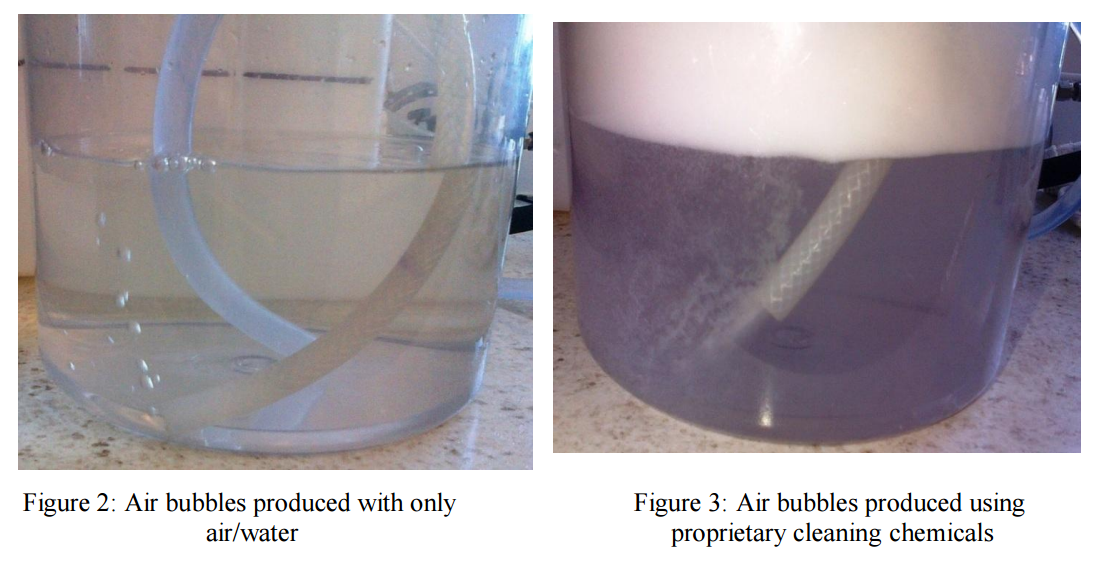
However, tests performed using proprietary cleaning chemicals in combination with a specially designed
bubble generator produced much smaller and more refined bubbles (Fig. 3 and 8). It was evident that
upon contact with proprietary cleaning chemicals, the size of the air bubbles was significantly reduced
This created a more turbulent cleaning solution, agitating the foulant on the membrane surface for ease
of removal.
In addition to modifying the size of the air inlet to vary bubble size, it has been observed that an increase
in the feed flow also increases the quantity of bubbles produced. Increasing the pump speed does not
necessarily give a proportional increase in the flow rate though when using the bubble generator device.
This was because as the pump speed was increased, the air intake also increases and so the cleaning
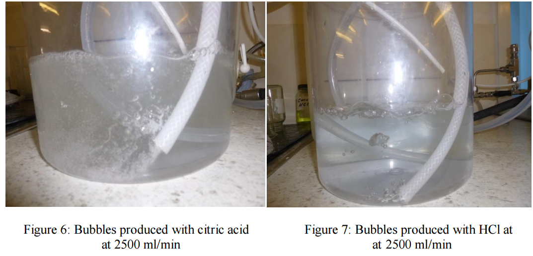
solution flow may even be reduced or stays the same after some value. Experiments on the flat sheet test
rig show that the use of a ventrui with a number of small tubes, together with a feed flow of 2000-2500
ml/min was needed to generate a sufficiently turbulent cleaning solution to facilitate foulant removal
(Fig. 4,5,6 and 7). It is important to note that a high enough feed velocity must be achieved to create a
steady flow of bubbles across the membrane surface. The increased turbulence within the membrane
element (boundary layer) with the air was achieved without the need of using any extra energy from the
CIP pumps of the RO rigs.

2.4 Experiments
Tests were carried out on:
a) Virgin membranes from different membrane manufacturers for compatibility testing.
b) Different types of fouled membranes for cleaning performance efficacy.
2.5 Autopsy
Autopsies were carried out on virgin and cleaned membranes to establish effect of cleaning with air and
effervescent chemicals. The autopsies were done in order to reveal membrane integrity and the amount
of foulant removed by cleaning. The autopsy involved visual inspection of the elements, Scanning
Electron Microscopy – Energy Dispersive X-ray Analysis (SEM-EDXA) and Infra-red to identify the
elemental composition of the foulants and examine integrity of the membrane surface, Fujiwara and dye
test for chemical, oxidation or physical damage of the membrane surface.
III. RESULTS
The results of cleaning are presented in another paper. This paper is focusing on the results of autopsies
from membranes that have undergone the cleaning process.
3.1 Flat Sheet Membrane Performance and Cleaning Studies
Standard Test Conditions are:
The flux rate is measured at standard operating conditions for each membrane type. The recirculation
rate was 1000 ml/min and normalised to 25 C.
The cleaning solution was recirculated @ 40 psi for 30 mins followed by a soak for 30 mins followed by
recirculation for desired cleaning time at 20 to 35 C.
The following cleans were carried out:
Table 2: Cleaning programs:
Clay and Iron fouled TFC-HR membrane:
1a Fouled membrane flux and salt rejection before clean
1b Performance after 0.5% NaOH for 3 hours, pH 12 @ temperature 35 ºC
1c Performance after 2% Citric for 2 hours, pH 2.5 @ temperature 20-25 ºC
2a Fouled membrane flux and salt rejection before clean
2b Performance after 0.5% NaOH + Air for 3 hours, pH 12 @ temp 35 ºC
2c Performance after 2% Citric + Air for 2 hours, pH 2.5 @ temp 20-25 ºC
3a Fouled membrane flux and salt rejection before clean
3b Performance after 1% Cleaner A for 3 hours, pH 12 @ temperature 35 ºC
3c Performance after 1% Cleaner B for 3 hours, pH 3.8 @ temp 20-25 ºC
4a Fouled membrane flux and salt rejection before clean
4b Performance after 1% Cleaner A + Air for 3 hours, pH 12 @ temp 35 ºC
4c Performance after 1% Cleaner B + Air for 3 hours, pH 3.8 @ temp 25-30 ºC
5a Fouled membrane flux and salt rejection before clean
5b Performance after 1% Cleaner C for 3 hours, pH 12 @ temperature 35 ºC
5c Performance after 1% Cleaner D for 3 hours, pH 2.7 @ temp 20-25 ºC
6a Fouled membrane flux and salt rejection before clean
6b Performance after 1% Cleaner C + Air for 3 hours, pH 12 @ temp 35 ºC
6c Performance after 1% Cleaner D + Air for 3 hours, pH 2.7 @ temp 25-30 ºC
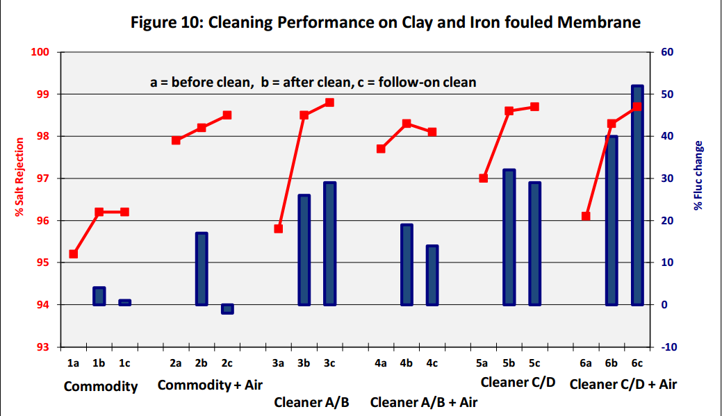
Results show that a combination of air bubbles, generated in situ with effervescent cleaning chemicals
enhances membrane performance, with an increase in both permeate flux and salt rejection (see Figure
10 above, Cleaners C and D are effervescent based cleaners). The cleaning effectiveness was also
revealed by visual inspection of membrane coupons before and after the cleaning tests. Closer
examination of the cleaned membrane coupons together with the performance data and subsequent
autopsy results, show that air bubbles did not cause any damage to the membrane surface. The Flat
Sheet Test Cell with the viewing window also demonstrated that the bubbles were evenly distributed
across the whole of the membrane area; thereby ensuring that the whole of the exposed fouled area was
cleaned.
3.2 Compatibility Tests with Virgin Flat Sheet Membranes and Bubbles
Comptibility tests were carried out using the Flat Sheet Rig with:
i) Saehan CSM 4040BE – brackish water polyamide membrane
ii) Filmtec BW30LE – brackish water polyamide membrane
iii) Trisep X-20 – low fouling brackish water polyamide membrane
iv) Trisep ACM2 – brackish water polyamide membrane
v) Trisep SB50 – cellulose acetate membrane
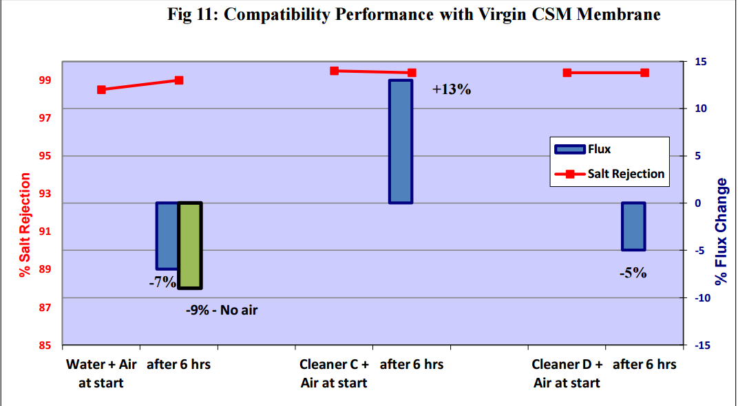
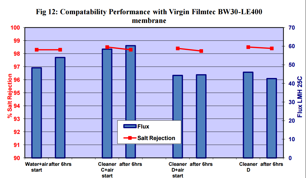
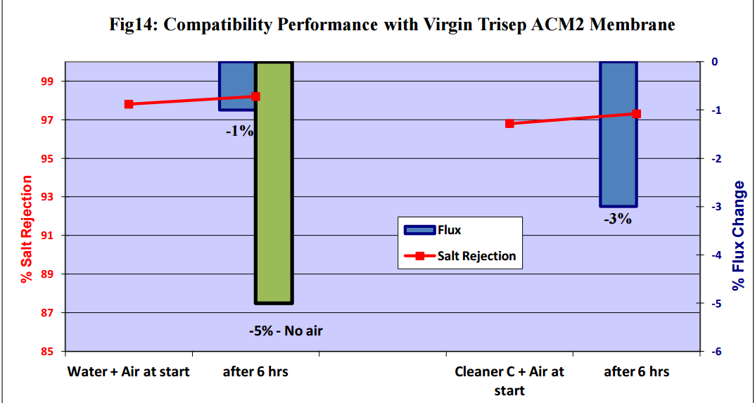
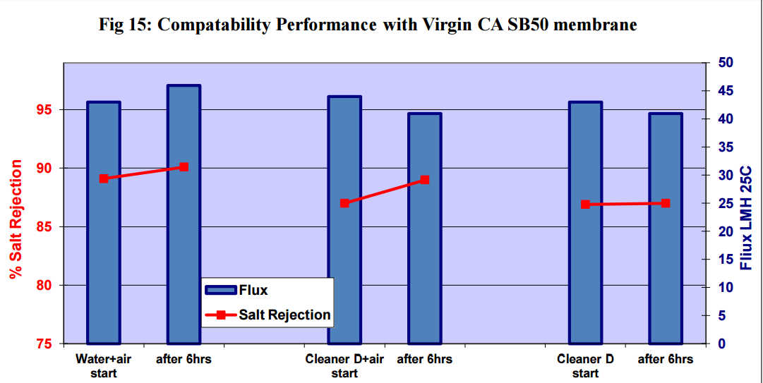
Figures 11 to 15 show that there was no significant flux or salt rejection loss after testing with virgin
CSM 4040BE, Filmtec BW30LE, Trisep X20, ACM2 and CA SB50 membranes with air and cleaning
chemicals. In fact, any flux loss was less than that obtained without air (ie, cleaning chemical or water
alone). The minor flux losses reported here (<10%) can be attributed to membrane compaction and
stabilization as these were virgin membrane samples.
3.3 Autopsy and Membrane Performance from Pilot Plant:
Results with Virgin Filmtec BW30-LE400 membrane and Virgin Koch TFC-HR membrane
read more at
http://www.genesysro.com/uploads/docs/SAFE-USE-OF-MICROBUBBLES-FOR-REMOVAL-OF-RO-MEMBRANE-FOULING-MAX.pdf